237 views
owned this note
# Specifications and Descriptions of the Mechanics and Services for the Mighty Pixel Tracker for the LHCb Tracking Simulation
We will need to produce a similification for easy simulation, but we need the material mass and location to be approximately correct.
We should roughly describe what is inside the acceptance [ 6 \times 5m^{2} ].
Objects at the C-frame do not need to be described. We can add it to the C-Frame material if needed.
NB: Things will likely be described as boxes or cylinders of similar material at this stage.
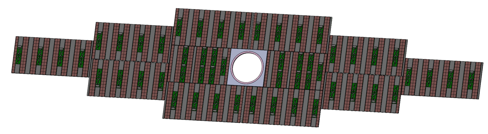
## Assembly of the MT Silicon modules (Low321 and Baseline Scenarios) V0.7
EDMS Folder - 3D CAD Models (Solidworks / STEP)
https://edms.cern.ch/document/2432309/1
For the Solidworks original files please see: 3124368
and for STEP files please see: 3124366
Screenshots/images :
https://indico.cern.ch/event/1429286/
Update - 3D CAD Model - Pixel Module Assembly, Chip matrix and services distribution
## External to the Sensor Area
### Fibres, Cables and Connectors
References? Diameter, material, length, relative placement. Simple CAD Model? Or simplified description
@Klaas and Dirk Aluminium cables
1. High Voltage Cable
2. High Voltage Connector
3. Low Voltage Cable
4. Low Voltage Connector
5. Optical Fibres
#### For LV cables:
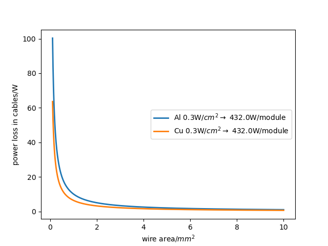
We would loose about 10W for 2mm^2 cables *2 for GND
***Cables for LV 2 with a total area 4mm^2 (incl, gnd)*** per module
For other cables:
```python
number_HV_cables=n_chains_p_module # =4
number_HDIs=16 #per module Mikes table
number_heatsens=number_HDIs*4 #4 wire sens
humidity_sens=1 *4 #per module 4 wire sens
number_thincables=number_heatsens+humidity_sens+number_HV_cables
awg38_area= 0.00811# in mm^2
```
--> ***thin cables 72 area thin cables 0.58392 mm^2** per module
number of connectors assume thin pcbs like this:
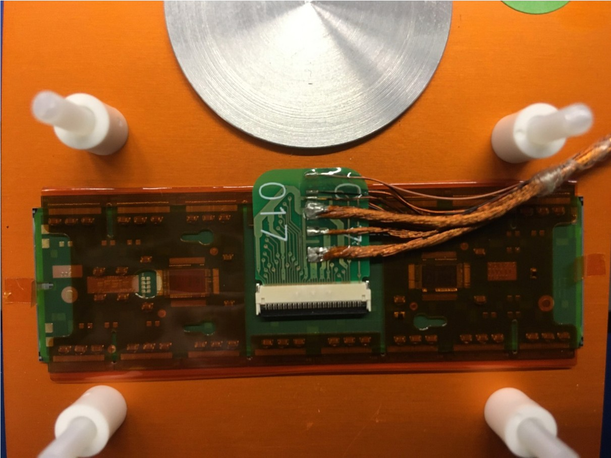
one per powerchain (4 per module)
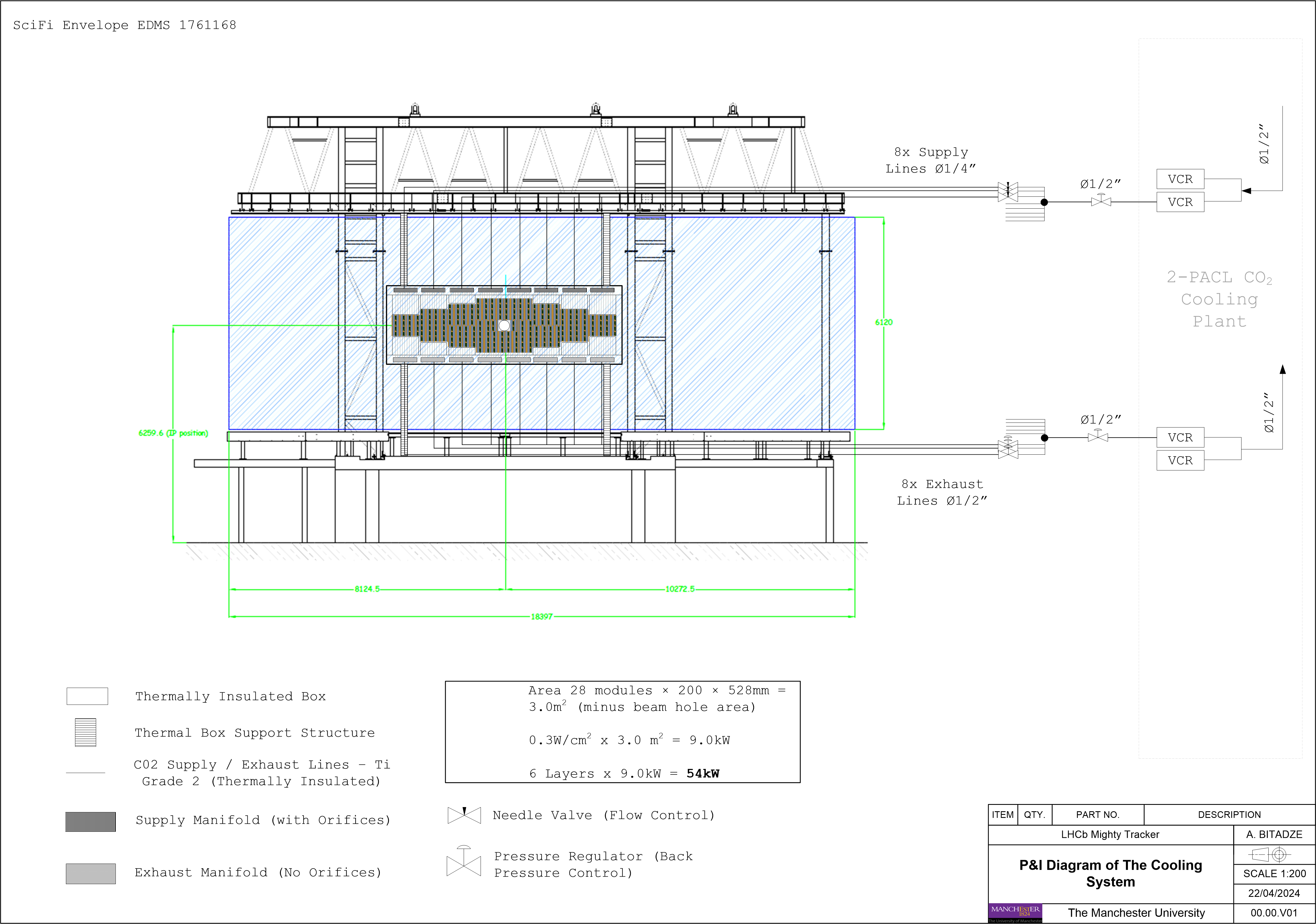
### P&I Diagram of The Cooling System.
References? Diameter, material, length, relative placement. Simple CAD Model?
@Alex will provide a Zero-th order design
1. C02 pipes from modules up to the C-Frame
2. Manifold
3. Connectors at the modules or box?

> Ok, this is great that there's a diagram now.
>
> What I need is a first guess from you what a simple supply and exhaust manifold looks like, and the supply and exhaust lines in the acceptance.
>
> And what kind of insulation surrounds these? Do you have some density values or link to similar insulation?
We have two options:
1. Passive thermal insulation - Armaflex https://local.armacell.com/fileadmin/cms/hongkong/products/en/Class0/ArmaFlex__C0-HK-EN-20201229-web.pdf
At least with 13mm Wall Thickness (a.k +26mm to OD of tubes)
Density - 80Kg/m3 https://local.armacell.com/fileadmin/cms/uk/products/en/HTArmaFlexIndustrialRangeUKROI.pdf
2. Active thermal insulation - Vacuum insulated concentric pipes. OD28mm external envelope for vacuum jacket for OD12mm pipes.
Please note active thermal insulation is expensive and not easy to maintain
For the advantages / disadvantages of Passive/Active insulation please see https://indico.cern.ch/event/287285/contributions/1640696/attachments/534388/736812/140630_TransferLines.pdf
>
> Best gut feeling, or examples are good enough for this first iteration.
>
> Just some cylinder or box cross section with inner and outer radii probably suffice for now. let's assume it's nicely welded titanium, each manifold is actually part of the module mechanics and we stick connectors on the long pipe going down somewhere.
>
Manifolds are part of the Cooling system and not module mechanics, they have to be considered as part of the overall cooling loop.
Preliminary design dimensions could be as following, but again all Pressure drops, flows and OD/IDs must be well understood...
> For example, I take Trevor's sketch:
> What are
>
> Manifold x1,x2,x3? Is it a box or a circular cross-section?
The length should be more or less same as module length (528mm) since we have to manifold internal pipes equally
For now please lets keep them square (since we don't know the orifice IDs and shapes)
X3 = 10mm (within this void we must have orifices for the supply manifold (not for exhaust), I cant define orifice dimensions yet)
X2 = 12mm (1mm wall thickness since they have to withstand 162Bar) (WT might increase depending on FEA results)
X1 = Manifolds do not need to be thermally insulated since they are sitting inside the thermal box.
> Supply Pipe r1, r2, r3 for insulation, pipe outer and inner radius?
Supply Lines = OD1/4” WT0.065"
Exhaust Lines = OD1/2” WT0.065”
+ Thermal insulation (see above) since these pipes are not inside the thermal box.
For the ALL properties of the Ti Pipes (OD/ID, density, WT, weight, pressure rating…) see below:
https://www.tubos.in/astm-b338-gr2-titanium-pipes-tubes-manufacturer.html
> Distribution pipe from manifold to module, r3, r4, r5
OD3mm WT160mu
They do not need to be thermally insulated since they are sitting inside the thermal box.
ALL tubes and manifolds must be Ti Grade 2
https://asm.matweb.com/search/SpecificMaterial.asp?bassnum=MTU020
Hope this helps
Cheers
Alex
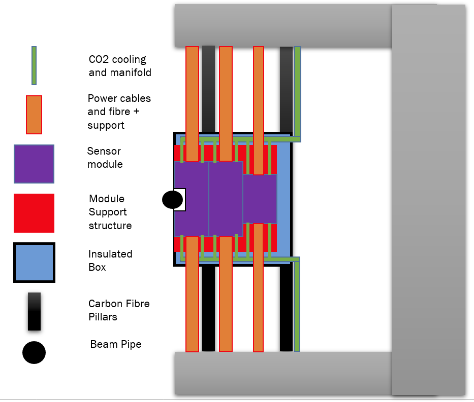
### Boxes/Frames and Standing/Hanging supports
References? Dimensions, material, relative placement, features. Simple CAD Model?
1. Box Shell for single and double layers. --> @Scott has a decription of Trevor's box
2. Internal Mechanical Supports--> @Trevor will add a material and estimate the mass
3. Box Mounting System to C-Frame--> @Trevor proposes two carbon fibre pillars a la IT
## Internal to the sensor Area
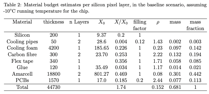
1. Add Tai-Hua's table and a simple version of Alex's CAD model of the sensor.
@Scott is the Armorflex foam and carbon fibre in the box material or the passive layer of the sensor? Probably move it to the box.
In my local description of the MP material, I have defined a new material for the BoxWall, consisting of Carbon Fiber, Armacell, plus a small fraction of epoxy. Should I also add a small fraction of copper for a faraday cage?