HIE-REX CAEN digitizer setup
============================
###### tags: `ISOLDE` `REX` `VME` `FESA` `DIGITIZER` `BSD`
## Class HREXDIGI setup
At the moment we have one V1724B (2014) card installed in cfv-170-bdbrex2 with 8 inputs.
The card has 8MB/ch of memory corresponding to 4 MS/ch and the custom input range option 10Vpp (±5V).
We also have a spare card V1724G (2017) 1MB/ch 256 kS/ch.
:::warning
The card installed has an old version of the firmware 4.02_128.29 (2014)
The legacy manual corresponds to 4.15_128.36 (2016)
:::
### Basic concepts for the CAEN V1724
The card is based on 8 100MS/s ADCs and an FPGA for the processing of the data. The FPGA firmware contains the code for the pulse hight analysis based on the *trapezoid filter*.
The acquired data is stored in internal buffers that are made ready for readout once they are complete.
The memory is divided in *aggregate* (programmable from 4 to 1024, also named *buffers* in some docs). Once an aggregate is ready (i.e. it has acquired all what it was supposed or it is flushed) it will be made available for readout.
For each aggregate one has to define the number of *events* to acquire, i.e. the number of triggers to record. The aggregate will not be ready for readout untill all the triggers have arrived (or is flushed).
Each event contains the data relative to one trigger, this can be waveform points, peak-energy value, timestamp of the trigger etc.
The values to use for the number of aggregate and for the number of events depend on the rate of triggers.
The number of samples is limited by the total memory of the board and on the acquisition mode (i.e. the number of size of fields in an event), such that
$$
\text{agg_num} \cdot \text{ev_num} \cdot \text{event_size} < \text{channel memory}
$$
The aggregate header is 8 bytes.
The size of each event is (8 + N_sample\*2) bytes (if both energy and time-stamp are enabled).
If 4 aggregate are selected with 1 event the maximum number of samples are thus (for the 1MB/ch board):
$$
\frac{\frac{1048576}{4}-8-6}{2} = 131065 ~\text{samples}.
$$
If dual probe is enabled half of the samples will be used by one probe and the other half by the other.
If the maximum number of aggregates is selected the maximum number of events (without any data samples and both energy and timestamp enabled) will be
$$
\frac{\frac{1048576}{1024}-8}{8} = 127 ~\text{events}
$$
:::warning
In fact the behaviour of the card is very strange and deviates from the doc.
With 32000 samples only 1 event works reliably. Any other value for nevent gives weird results. When the number of samples is small the number of events can be larger.
:::
### Selecting a silicon detector
* HREX.DIG.V1724/Setting#**channelMask** val (e.g. 0x01 for XLN2)
* 0x01: XLN2.BSD.0300
* 0x02: XT00.BSD.1300
* 0x04: XT00.BSD.1050
* 0x08: XLIHS.BSD.0100
* 0x10: XT00.BSD.1900
* 0x20: XT02.BSD.0400
* 0x40: XT01.BSD.0400
* 0x80: XT03.BSD.0400
:::info
Although it is possible to acquire multiple channels in parallel (just OR the values) it is suggested to only enable one channel at a time
:::
* HREX.DIG.V1724/ChannelSetting#**dac** value
This offsets the input extending the range available for the signal (which is positive-unipolar).
The *value* is an unsigned 16 bit integer (0-65535 -> ±5V).
For a centerd range of the ADC the DAC should be set to mid-scale (32767).
In our case, positive-unipolar signal, the DAC value should be set close to 60000.
:::danger
If the input signal is under or over range the auto-triggering fails.
It is important to adjust the DAC offset correctly and limit the input amplitude.
:::
* HREX.DIG.V1724/Setting#**triggerSource** **EXTERNAL**
This enables the external trigger provided by an LTIM.
* HREX.DIG.V1724/Setting#**operationMode** **ENABLE**
This defines how the card is read out and how the FESA fields are filled.
The operational value to use is ENABLE. There are also the EXPERT_RAW and DISABLE modes (no information about).
### Enabling the oscilloscope mode
In this mode the digitizer is setup in order to acquire the input signal directly using:
* the minimum number of aggregators (4)
* one event per aggregator (max event size of 262144 bytes)
* number of data points per event up to 131064 (1.3ms)
#### Board settings
* HREX.DIG.V1724/**StopAcquisition**
Stops the acquisition (if running).
* HREX.DIG.V1724/**MemoryClear**
Clears the memory structures of the digitizer.
* HREX.DIG.V1724/Setting#**chconfiguration**
Sets various acquisition parameters. Normally only bit 16 (Scope_Mode) has to be changed.
:::warning
**TODO** It looks like the analog probes 1 and 2 are inverted and disabling dual trace breaks the readout.
The digital probes are also not handled correctly in FESA in case dual trace is disabled.
:::
* bit 0 Automatic data flush: 0
* bit 1 RESERVED: 0
* bit 2 Trigger propagation: 1
* bit 3 RESERVED: 0
* bit 4 RESERVED: 1
* bit 5 RESERVED: 0
* bit 6 RESERVED: 0
* bit 7 RESERVED: 0
* bit 8 Individual_Trg_Mode: 1
* bit 9 RESERVED: 0
* bit 10 RESERVED: 0
* bit 11 Dual_Trace: 1
* bit 12 Virtual_Probe_1_0: 1
* bit 13 Virtual_Probe_1_1: 1
* 00: Input
* 01: RC-CR (input 1st derivative)
* 10: RC-CR2 (input 2nd derivative)
* 11: Trapezoid (output of the trapezoid filter)
* bit 14 Virtual_Probe_2_0: 0
* bit 15 Virtual_Probe_2_1: 0
* 00: Input
* 01: Threshold, which is referred to the RC-CR2 signal
* 10: Trapezoid - Baseline
* 11: Baseline (of the trapezoid)
* **bit 16 Scope_Mode: 1**
* bit 17 Energy_Mode: 1
* bit 18 Time_Tag_Mode: 0
* bit 19 RESERVED_19_0: 0
* bit 20 Digital_Probe_1_0:
* bit 21 Digital_Probe_1_1:
* bit 22 Digital_Probe_1_2:
* bit 23 Digital_Probe_1_3:
* 0000: ”Peaking”, shows where the energy is calculated
* 0001: ”Armed”, digital input showing where the Timing Filter crosses the Threshold
* 0010: ”Peak Run”, starts with the trigger and last for the whole event
* 0011: ”Pile-up”, shows where a pile-up event occurred
* 0100: ”Peaking”, shows where the energy is calculated
* 0101: ”Trg Validation Win”, digital input showing the trigger validation acceptance window TVAW
* 0110: ”Baseline freeze”, shows where the algorithm stops calculating the baseline and its value is frozen
* 0111: ”TRG Holdoff”, shows the trigger hold-off parameter
* 1000: ”Trg Validation”, shows the trigger validation signal TRG_VAL
* 1001: ”Acq Busy”, this is 1 when the board is busy (saturated input signal or full memory board) or there is a veto
* 1010: ”Zero Cross. Win.”, shows the Zero Crossing Acceptance Windows width
* 1011: ”Ext TRG”, shows the external trigger, when available
* 1100: ”Busy”, shows when the memory board is full
* 1101: ”Peak Ready”, shows after the Peak Mean time
* bit 24 Event_Data_Format: 1 (Enable the FORMAT Word in the aggregate data)
* bit 25 RESERVED: 0
* bit 26 Digital_Probe_2_0: (only in the new version of the doc)
* bit 27 Digital_Probe_3_1:
* bit 28 Digital_Probe_4_2:
* 000: "Trigger", position of the trigger
* bit 29 RESERVED: 0
* bit 30 RESERVED: 0
* bit 31 RESERVED: 0
* HREX.DIG.V1724/Setting#**bufferOrganization** NBLK_4
Sets the number of aggregates to the minimum (4)
* HREX.DIG.V1724/Setting#**samplesNumber** 32000
Sets the number of *locations* per event, this value is really n_samples/2 for a single probe and n_samples for dual probe.
* HREX.DIG.V1724/Setting#**clearaftereading** **True**
This performs a soft clean after each readout cycle
#### Channel settings
* HREX.DIG.V1724/ChannelSetting#**triggerThreshold** **4000**
Threshold value in ADC bits (after the trigger pulse has passed trough the RC-CR2 filter)
:::info
GUESS:
If the external trigger is used this value has no effect
:::
* HREX.DIG.V1724/ChannelSetting#**numEvent** 1
Set the number of events per aggregate to 1.
Only one trigger sequence will be acquired per acquisition cycle.
* HREX.DIG.V1724/**StartAcquisition**
### Enabling histrogram mode
In this mode the digitizer is setup in order to acquire the pulses from the Silicon detector using:
* the maximum number of aggregate (1024)
* one event per aggregate (max event size of 262144 bytes)
* number of data points per event up to 131064 (1.3ms)
#### Board settings
* HREX.DIG.V1724/**StopAcquisition**
Stops the acquisition (if running).
* HREX.DIG.V1724/**MemoryClear**
Clears the memory structures of the digitizer.
* HREX.DIG.V1724/Setting#**samplesNumber** **1**
:::info
This value should be set to a larger value and use the virtual probe for setting up the varius acquisition parameters (filter coefficients etc.).
Different amplifiers and different detector require different settings.
Instead of setting to 1 may be it would be better to turn off the scope mode (see below).
:::
* HREX.DIG.V1724/Setting#**clearaftereading** **False**
#### Channel settings
* HREX.DIG.V1724/ChannelSetting#**triggerThreshold** val
**40** for small SD
between **60** and **80** for big SD
:::info
The coefficients of the RC-CR2 should be adjusted first
:::
* HREX.DIG.V1724/ChannelSetting#**numEvent** val
From **1** to **1000** depending on the rate (1 for very small rates)
* HREX.DIG.V1724/Setting#chconfiguration
See above for the details. The important bits are:
* bit 16 **Scope_Mode True** (really?)
* bit 17 **Energy_Mode True**
* bit 18 **Time_Tag_Mode True**
* HREX.DIG.V1724/Setting#**bufferOrganization** value
**NBLK_64** is used so far by OP-application.
It could be increased up to NBLK_1024, but it depends on the number of events and number of samples.
* HREX.DIG.V1724/**StartAcquisition**
## Readout
### BOARD AGGREGATE
The memory is divided into aggregates, to read the data the EventReadoutBuffer is used (at offset 0x000).
The readout is in units of 32-bit-lwords and the structure of the data is:
#### “BOARD AGGREGATE” DATA FORMAT
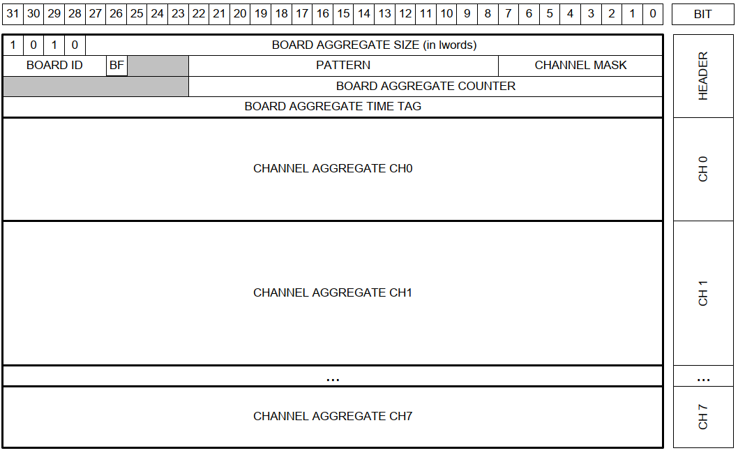
The total size of an event depends on the size (samples) of the waveforms
* BOARD AGGREGATE SIZE: total size of the aggregate.
* BOARD ID: corresponds to the GEO address of the board. In case of VME64X boards this number is automatically set for each board. In case of VME boards this value is by default = 0 for all boards. It is possible to set the GEO address of the boards using register 0xEF08, which is quite useful in case of concatenate BLT (CBLT) read.
* BF: Board Fail flag. This bit is set to “1” after a hardware problem, as for example the PLL unlocking, or over-temperature condition. The user can investigate the problem checking the error monitor register 0x8178. Meaningful only for ROC FPGA firmware revision greater than 4.5.
* PATTERN: is the value read from the LVDS I/O (VME only).
* CHANNEL MASK: corresponds to those channels partecipating to the Board Aggregate.
* BOARD AGGREGATE COUNTER: counts the board aggregate. It increases with the increase of board aggregates.
* BOARD AGGREGATE TIME TAG: is the time of creation of the aggregate (this does not correspond to any physical quantity).
### CHANNEL AGGREGATE
Each channel aggregate contains a predefined number of event for that channel, we use 1 event only to allow the immediate readout seen the low and inpredictable rate of events.
#### "CHANNEL AGGREGATE" DATA FORMAT
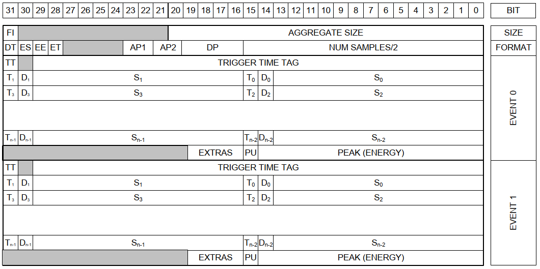
* FI: when 1, the second word is the Format Info
* DT: Dual trace enabled flag (0 = disabled, 1 = enabled)
* ES: Waveform (samples) enabled flag
* EE: Energy enabled flag
* ET: Trigger Time Stamp enabled flag
* AP1: Analog Probe 1 Selection. AP1 can be selected among:
* 00 = “Input”: the input signal from pre-amplified detectors
* 01 = “RC-CR”: first step of the trigger and timing filter
* 10 = “RC-CR2”: second step of the trigger and timing filter
* 11 = “Trapezoid”: trapezoid resulting from the energy filter
* AP2: Analog Probe 2 Selection. AP2 can be selected among:
* 00 = “Input”: the input signal from pre-amplified detectors
* 01 = “Threshold”: the RC-CR2 threshold value
* 10 = “Trapezoid-BL”: the trapezoid shape minus its baseline
* 11 = “Baseline”: displays the trapezoid baseline
* DP: Digital Virtual Probe Selection. DP can be selected among:
* 0000 = “TRG Window”: shows the RT Discrimination Width
* 0001 = “Armed”: digital input showing where the RC-CR2 crosses the Threshold
* 0010 = “Peak Run”: starts with the trigger and last for the whole event
* 0011 = “Pile-Up”: shows when there is a pile-up event and corresponds to the time interval when the energy calculation is disabled due to the pile-up event
* 0100 = “Peaking”: shows where the energy is calculated
* 0101 = “Trg Validation Win”: digital input showing the trigger validation acceptance window TVAW
* 0110 = “BSL Holdoff: shows the baseline hold-off parameter
* 0111 = “TRG Holdoff”: shows the trigger hold-off parameter
* 1000 = “Trg Validation”: shows the trigger validation signal TRG_VAL
* 1001 = “Acq Veto”: this is 1 when either the input signal is saturated or the memory board is full
* TT: Trigger Type (0=self-trigger, 1=external trigger)
* Sm (m = 0, 2, 4n – 2): Even Samples of AP1 at time t = m
* Sm′ (m′ = 1, 3, 4n – 1): if DT=0, then Sm′ corresponds to the odd Samples of AP1 at time t = m′. Otherwise, if DT=1, they correspond to the even Samples of AP2 at time t = m′ – 1
* Tn: bit identifying in which sample the Trigger occurred
* Dn: Digital Virtual Probe for each sample. The Probe type can be read from the “DP” field in the header
* PU: Pile Up. This bit is usually set to zero. The user can recognize a pile up event when also the Energy value is zero. The user can also choose to have this bit equal to 1 in case of pile-up event, by enabling bit[27] of 0x1n80 register address. In that case, the energy value is what read from the algorithm
* EXTRAS: bit[0] = DEAD_TIME. This is set to 1 when a dead time occurred before this event. The dead time can be due to either a signal saturation or a full memory status.
* bit[1] = ROLL_OVER. Identify a trigger time stamp roll-over that occurred before this event
* bit[2] = TT_RESET. Identify a trigger time stamp reset forced from external signals in S-IN (GPI for Desktop)
* bit[3] = FAKE_EVENT. This is a fake event (which does not correspond to any physical event) that identifies a time stamp roll-over. The roll-over can be due to an external or internal reset. The user can set bit[25] = 1 of register 0x1n80 to enable the fake-event saving in case of reset from S-IN, and bit[26] = 1 of register 0x1n80 to enable the fake-event saving in case of internal roll-over. In the first case the event will have both bit[3] and bit[2] set to 1, while in the second case the event will have both bit[3] and bit[1] set to 1.
:::warning
The samples of the analog probes can be signed or unsigned. The Input signal is unsigned (unipolar ADC output), while the othet signals (computed) are signed and need to be adjusted:
```val = reg & 0x2000 ? reg - 0x4000 : reg```
:::
:::warning
The RC-CR2 threshold register has a scale that is twice that of the analog probes. One should define the threshold on the probe signal and then set a value twice as large in the threshold register.
:::
### Notes
Reference documents:
* UM5407_724-781_DPP_PHA_Legacy_Registers_rev3.pdf (Multi channel analyzer FW).
* UM5918_724_Registers_Description_rev2.pdf (base board manual).
Registers not documented in CAEN MCA manual, but used in the driver.
* READOUT_BUFFER: Offset 0, found in base board manual, but size does not match (0x400 w.r.t. 0xffc).
* V_CustomSize: Offset 0x8020, found in base board manual.
* V_BufferFree: Offset 8010, *Frees the first N Output Buffer Memory Blocks*, undocumented.
* ChN_BuffOccup: Offset 1n94, *Number of occupied buffers*, undocumented.
* ChN_CUST_SIZE: Offset 1n20, *Number of samples in the waveform*, undocumented.
### Various
#### E-mail to Emiliano 23.08.2021
Hi,
I changed a bit the HREXDIGI class. The readout now works a bit differently.
Important things are:
Scope mode:
Set Setting#bufferOrganization to the minimum value, Setting#samplesNumber to a large value (the max size of the trace arrays is 32768), ChannelSettingN#numEvent to 1 and set Setting#chConfiguration:Scope_mode
The trace decoding has been fixed so now probe1 and probe2 correspond to the settings in Setting#chConfiguration, i.e. if Dual_Trace is enabled probe1 and probe2 are inverted w.r.t. the old behaviour (this difference is due to an error in the CAEN docs or in their FW)
Energy or counting mode:
Set Setting#bufferOrganization to the maximum value and ( Setting#samplesNumber to a value<100 or clear Setting#chConfiguration:Scope_mode or both), if Scope_mode if false samplesNumber is in-influent.
Set Setting#chConfiguration:Energy_Mode and Setting#chConfiguration:Time_Tag_Mode. The time tag of the events is necessary for the calculation of the count rate, without that you only know the number of counts, but without any information on the time it took to integrate it.
Adjust the threshold in ChannelSettingN#triggerThreshold and ChannelSettingN#numEvent (with Setting#bufferOrganization x ChannelSettingN#numEvent < 1e6 ) numEvent should be 1/10 to 1/100 of the expected count rate to avoid the readout hanging waiting for pulses, better to put a small value to start with and then increase if necessary.
In both cases set Setting#triggerSource to EXTERNAL_TRIGGER only. I have seen that if this is OFF sometime the acquisition does not start even if particles arrive.
On the other hand the CHN bits only enable the different channels to trigger global triggers (i.e. all channels), which we do not need/want, the trigger for the channel that receives the pulse is happening even if these bits are 0 (so these are useful only if you want to do coincidence counting or similar)
Until now only one aggregate was read per second (corresponding to ChannelSettingN#numEvents particles), now if the trace size is <100 it reads out consecutive aggregates (if available) for up to 700ms (then gives up to publish the data).
This has three effects
The histogram build up is less dependent on numEvents, so you can keep it smaller
The histogram buildup should be faster
It is possible to calculate reliable count rates independently of the numEvents parameter
Cheers,
Enrico